All ns-3 releases are archived: the short links below provide
quick access to the source code, releases notes, and documentation of
every past release:
Releases
| ns-3.11 (May 2011) | ns-3.10 (January 2011) | |
| ns-3.9 (August 2010) | ns-3.8 (May 2010) | ns-3.7 (January 2010) |
| ns-3.6 (October 2009) | ns-3.5 (July 2009) | ns-3.4 (April 2009) |
| ns-3.3 (December 2008) | ns-3.2 (September 2008) | ns-3.1 (July 2008) |
Releases
We strive to ship a new stable release once every trimester:
each new release contains new features, bugs fixed, and ships with
extensive documentation such as a tutorial, manual, etc.
- Latest release: the source code tarball, list of new features, and documentation for the latest release.
- Older releases are archived for those who might need them.
- The development tree is available for those who intend to contribute to the project or those who need to use the bleeding edge version of ns-3.
How to install ns-2.34 on Ubuntu 9.10 Karmic Koala

If you are planning to install the latest ns-2.34 on Ubuntu 9.10 Karmic Koala, here are some basic steps
1. Download ns-allinone-2.34.tar from here.
2. Place it in somewhere, e.g. /home/simulator, then extract it.
$ cd /home/simulator
$ tar -xvf ns-allinone-2.34.tar
3. Download & install some packages from repository
$ sudo apt-get install build-essential autoconf automake libxmu-dev
4. Install the ns2
$ cd ns-allinone-2.34
$ ./install
5. You might face problem with the installation of otcl-1.13, the problemcan be due to the gcc-4.4.1 / g++-4.4.1 compilers. But please try this :
sudo apt-get install g++-4.3
CC=gcc-4.3 CXX=g++-4.3 ./install
try to edit the Makefile.in too
From :

CC= @CC@


to :

CC= gcc-4.3
6. Edit some paths ==a
$ gedit ~/.bashrc
Put these lines on that file. Off course, you might change /home/simulatorfor it depends on where you extract ns-allinone-2.34.tar.
# LD_LIBRARY_PATH
OTCL_LIB=/home/simulator/ns-allinone-2.34/otcl-1.13
NS2_LIB=/home/simulator/ns-allinone-2.34/lib
X11_LIB=/usr/X11R6/lib
USR_LOCAL_LIB=/usr/local/lib
export LD_LIBRARY_PATH=$LD_LIBRARY_PATH:$OTCL_LIB:$NS2_LIB:$X11_LIB:$USR_LOCAL_LIB
# TCL_LIBRARY
TCL_LIB=/home/simulator/ns-allinone-2.34/tcl8.4.18/library
USR_LIB=/usr/lib
export TCL_LIBRARY=$TCL_LIB:$USR_LIB
# PATH
XGRAPH=/home/simulator/ns-allinone-2.34/bin:/home/simulator/ns-allinone-2.34/tcl8.4.18/unix:/home/simulator/ns-allinone-2.34/tk8.4.18/unix
NS=/home/simulator/ns-allinone-2.34/ns-2.34/
NAM=/home/simulator/ns-allinone-2.34/nam-1.13/
export PATH=$PATH:$XGRAPH:$NS:$NAM
7. Validate it
$ cd ns-2.34
$ ./validate
7. (Optionally) You can create a symlink, so that ns can be called from everywhere
$ sudo ln -s /home/simulator/ns-allinone-2.34/ns-2.34/ns /usr/bin/ns
8. Try to run it.
$ ns

If you are planning to install the latest ns-2.34 on Ubuntu 9.10 Karmic Koala, here are some basic steps
1. Download ns-allinone-2.34.tar from here.
2. Place it in somewhere, e.g. /home/simulator, then extract it.
$ cd /home/simulator
$ tar -xvf ns-allinone-2.34.tar
3. Download & install some packages from repository
$ sudo apt-get install build-essential autoconf automake libxmu-dev
4. Install the ns2
$ cd ns-allinone-2.34
$ ./install
5. You might face problem with the installation of otcl-1.13, the problemcan be due to the gcc-4.4.1 / g++-4.4.1 compilers. But please try this :
sudo apt-get install g++-4.3
CC=gcc-4.3 CXX=g++-4.3 ./install
try to edit the Makefile.in too
From :
CC= @CC@
to :
CC= gcc-4.36. Edit some paths ==a
$ gedit ~/.bashrc
Put these lines on that file. Off course, you might change /home/simulatorfor it depends on where you extract ns-allinone-2.34.tar.
# LD_LIBRARY_PATH
OTCL_LIB=/home/simulator/ns-allinone-2.34/otcl-1.13
NS2_LIB=/home/simulator/ns-allinone-2.34/lib
X11_LIB=/usr/X11R6/lib
USR_LOCAL_LIB=/usr/local/lib
export LD_LIBRARY_PATH=$LD_LIBRARY_PATH:$OTCL_LIB:$NS2_LIB:$X11_LIB:$USR_LOCAL_LIB
# TCL_LIBRARY
TCL_LIB=/home/simulator/ns-allinone-2.34/tcl8.4.18/library
USR_LIB=/usr/lib
export TCL_LIBRARY=$TCL_LIB:$USR_LIB
# PATH
XGRAPH=/home/simulator/ns-allinone-2.34/bin:/home/simulator/ns-allinone-2.34/tcl8.4.18/unix:/home/simulator/ns-allinone-2.34/tk8.4.18/unix
NS=/home/simulator/ns-allinone-2.34/ns-2.34/
NAM=/home/simulator/ns-allinone-2.34/nam-1.13/
export PATH=$PATH:$XGRAPH:$NS:$NAM
7. Validate it
$ cd ns-2.34
$ ./validate
7. (Optionally) You can create a symlink, so that ns can be called from everywhere
$ sudo ln -s /home/simulator/ns-allinone-2.34/ns-2.34/ns /usr/bin/ns
8. Try to run it.
$ ns
Università degli Studi di Napoli Federico II
Adapting BitTorrent to wireless ad hoc networks
By : Mohamed Karim Sbai, Chadi Barakat, Jaeyoung Choi,
Abstract:
BitTorrent is one of the Internet's most efficient content distributionprotocols. It is known to perform very well over the wired Internet where end-to-end performance is almost guaranteed. However, inwireless ad hoc networks, many constraints appear as the scarcity of resources and their shared nature, which make running BitTorrent with its default configuration not lead to best performances. To these constraints it adds the fact that peers are both routers and end-users and that TCP-performance drops seriously with the number of hops. We show in this work that the neighbor selection mechanism in BitTorrent plays an important role in determining the performance of the protocol when deployed over a wireless ad hoc network. It is no longer efficient to choose and treat with peers independently of their location. A first solution is to limit the scope of the neighborhood. In this case, TCP connectionsare fast but there is no more diversity of pieces in the network: pieces propagate in a unique direction from the seed to distant peers. This prohibits peers from reciprocating data and leads to low sharing ratios and suboptimal utilization of network resources. To recover from these impairments, we propose an enhancement to BitTorrent which aims to minimize the time to download the content and at the same time to enforce cooperation among peers. Our solution considers a restricted neighborhood to reduce routingoverhead and to improve throughput, while establishing fewconnections to remote peers to improve diversity of pieces. With the help of extensive NS-2 simulations, we show that these enhancements to BitTorrent significantly improve the file completion time while fully profiting from the incentives implemented in BitTorrent to enforce fair sharing.
Mohamed Karim Sbai, Chadi Barakat, Jaeyoung Choi, Anwar Al Hamra, Thierry Turletti, "Adapting BitTorrent to wireless ad hoc networks" to appear in proceedings of 7th International conference on ad hoc networks and wireless 2008 (AD-HOC NOW), Sophia Antipolis, France, September 2008. download
NS-2 Simulator code and scripts:
Click here to download code.
Mannasim : Wireless Sensor Networks simulation environment

Mannasim is a Wireless Sensor Networks simulation environment comprised of two solutions:
- the Mannasim Framework;
- the Script Generator Tool.
The Mannasim Framework is a module for WSN simulation based on theNetwork Simulator (NS-2). Mannasim extends NS-2 introducing new modules for design, development and analysis of different WSNapplications.
The Script Generator Tool (SGT) is a front-end for TCL simulation scripts easy creation. SGT comes blunded with Mannasim Framework and it's written in pure Java making it plataform independent.
Mannasim Objectives
Mannasim goal is to develop a detailed simulation framework, which can accurately model different sensor nodes and applications while providing a versatile testbed for algorithms and protocols.
Numerous challenges make the study of real deployed sensor networks very difficult and financially infeasible. At the current stage of the technology, a practical way to study WSNs is through simulations that can provide a meaningful perspective of the behavior and performance of various algorithms.
Extended Nam Editor

Mannasim is a Wireless Sensor Networks simulation environment comprised of two solutions:
- the Mannasim Framework;
- the Script Generator Tool.
The Script Generator Tool (SGT) is a front-end for TCL simulation scripts easy creation. SGT comes blunded with Mannasim Framework and it's written in pure Java making it plataform independent.
Mannasim Objectives
Mannasim goal is to develop a detailed simulation framework, which can accurately model different sensor nodes and applications while providing a versatile testbed for algorithms and protocols.Numerous challenges make the study of real deployed sensor networks very difficult and financially infeasible. At the current stage of the technology, a practical way to study WSNs is through simulations that can provide a meaningful perspective of the behavior and performance of various algorithms.
Extended Nam Editor
Donato Emma - Roberto Canonico - Giorgio Ventre
The Extended Nam Editor is an editor that allows the graphical creation of ns2 scripts. It extends the basic Nam Editor with the following features:
- Integration with existing topology generators
- Localization and visualization of set of nodes on large network topologies according to different selection criteria;
- Instantiation of agents of any types on all the nodes of a given node set;
- Definition of new node types;
- Support for simulations of web cache systems.
Topology Generator Interface
The manual generation of complex Network Topology is a tedious and error prone activity.In order to simulate networks with realistic topologies, it is a common practice to use ad-hoc topology generators, whose output is usually not compatible with the ns2 syntax. Hence, several tools have been developed to translate topology descriptions generated by topology generators in ns-scripts that can be used in the definition of a simulation scenario.
Unfortunately, scripts produced in this way are not compatible with the Nam Editor, hence networks created by common topology generators cannot be modified interactively. Such a limitation is sometimes annoying, in particular when the automatically generated topology needs to be further adapted, e.g. by instantiating agents on particular network nodes.
Our extended Nam-Editor provides a graphical interface to:
- GT-ITM topology generator;
- INET topology generator;
- flat-itm;
- hierarchical-itm;
- transit-stub-itm;
- INET;
- select a generation method from the generator list (see fig.1);
- click the "Topology Generation" button (see fig.1);
- fill in a generator-specific input masks, in order to provide the selected generator with the required parameters (see fig. 2; for the meaning of these parameters, please refer to the generators documentation);
- click the "Create Topology" button (see fig.2);
 Fig. 1: Topology Generation
Node Set Tool
Localization of a network agent in a simulation scenario is a two steps process, which requires:- the localization of the node in which the agent must be instantiated;
- the instantiation of the agent.
A Node Set is a set of nodes selected according to one of the following criteria:
- leaf node;
- mutual distance;
- randomly.
- visualize all the nodes included in a given set;
- associate a color to all the nodes included in a given set;
- instantiate an agent on all the nodes of a given set;
- instantiate a Web Server on all the nodes of a given set (See Web Tool);
- instantiate a Web Client on all the node of a given set (See Web Tool);
- instantiate a Web Cache on all the node of a given set (See Web Tool);

Editor Configuration
The ns2 is an extensible network simulator.New protocols can be simulated through the definition of a new Agent type.
Likewise, particular network scenarios may require the definition of new Node types.
The GUI of our Extended Nam Editor can be customized to:
- add an user-defined agent to the agent list;
- customize the parameters of a user-defined agent;
- define new node type and its parameters;
- associate a particular node type to any node.
- select the "Configure Editor" entry from the Edit menu;
- click the "Define New Agent" button (see fig. 4);
- fill in the new agent mask and click the "Continue" button (see fig. 4);
- define the Name and the Default value for any agent parameter (see fig. 5);
- click the "Continue" button (see fig. 5).
 Fig. 4: New Agent mask
Web Tool
A special support as been provided in our Extended Nam Editor for simulating web cache systems. A proper tool (see fig. 6) can be used to create web-page pools and to deploy system of caches, servers and clients onto a previously generated topology.
The configuration of any web element is made through a configuration window (see fig. 7); for the meaning of the parameters included in this window please refer to the ns Manual.

Install instructions
If you start from the source distribution:- cd to your ns-allinone
- remove the nam-1.0a11 directory (rm -rf nam-1.0a11)
- expand the ext-nam-1.0a11.tar.gz archive (tar xzvf ext-nam-1.0a11.tar.gz)
- cd nam-1.0a11
- build the extended nam editor (./configure; make clean; make)
- expand the ext-nam-1.0a11.gz file (gunzip ext-nam-1.0a11.gz);
- put the nam binary in your path.
NS-2 Emulation Extensions

Thenetwork simulator ns-2 is a widely accepted discrete event networksimulator, actively used for wired and wireless network simulations. It has a highy detailed model of the lower layers (Physical and MAC) of wireless IEEE 802.11 networks.
Ns-2 has also an emulation feature, i.e. the ability to introduce thesimulator into a live network and to simulate a desired network between real applications in real-time.
Within the scope of this project we developed some methods and extensions to the ns-2 to combine wireless network simulation and network emulation. Now ns-2 can emulate an arbitrary IEEE 802.11 network between real applications. Furthermore, our extensions are generic, i.e. can be applied to any network supported in the ns-2.
NS-2 emulation extensions use two methods for network emulation: Single Host and Distributed Clients. In the first method the simulator and all theapplications run on one computer. We use User-Mode-Linux virtual machines and emulate a ns-2 netwok among them. The applications run inside the virtual machines and do not notice that they communicate through a simulated network.
In the Distributed Clients method we run the applications and thesimulator on separated machines for better scalability. Here we use TUN/TAP virtual network interfaces and map them to nodes in the ns-2simulator. The network among these TUN/TAP interfaces is again simulated. The applications interact with it in the same way they would interact with a real network.
More Info.
tags : network simulator ns2 emulation extension physical layer MACwireless
Apr 30, 2007
Extended Network Simulator NS-2 Nam Editor

The Extended Nam Editor is an editor that allows the graphical creation of ns2 scripts. It extends the basic Nam Editor with the following features:
- Integration with existing topology generators
- Localization and visualization of set of nodes on large network topologies according to different selection criteria;
- Instantiation of agents of any types on all the nodes of a given node set;
- Definition of new node types;
- Support for simulations of web cache systems.
Topology Generator Interface
The manual generation of complex Network Topology is a tedious and error prone activity.
In order to simulate networks with realistic topologies, it is a common practice to use ad-hoc topology generators, whose output is usually not compatible with the ns2 syntax. Hence, several tools have been developed to translate topology descriptions generated by topologygenerators in ns-scripts that can be used in the definition of a simulation scenario.
Unfortunately, scripts produced in this way are not compatible with the Nam Editor, hence networks created by common topology generatorscannot be modified interactively. Such a limitation is sometimes annoying, in particular when the automatically generated topology needs to be further adapted, e.g. by instantiating agents on particular network nodes.
Nam-Editor provides a graphical interface to:
- GT-ITM topology generator;
- INET topology generator;
It is now possible to create, visualize and modify topologies created according to the following topology models:
- flat-itm;
- hierarchical-itm;
- transit-stub-itm;
- INET;
More info here
Vehicular Network Simulation
The Vehicular Network Simulations (VANET/ITS) have been carried out using VanetMobiSim and Ns-2 tools. Most of the simulations are about VANETS (Vehicular Ad-hoc NETworks), thus the communication between the vehicles are achieved by using only ad-hoc operation mode of the IEEE 802.11b MAC Layer Standard.
Title Format
Accuracy and Efficiency in Simulating VANETs.http://carlink.lcc.uma.es/doc/MCO08/MCO_Articulo/Accuracy_and_Efficiency_in_Simulating_VANETs.pdf
Enrique Alba, Sebastián Luna, and Jamal Toutouh
Vehicular Data Transfer Protocol (VDTP) - Ns-2 Installation. http://www.4shared.com/file/PVAY1lhZ/VDTP-Installation.html
Needed to simulate most of the examples you can download.
Simulation and evaluation of realistic VANET communications in CARLINK scenarios.http://carlink.lcc.uma.es/doc/provis/D1.3.9-Simulation%20and%20evaluation%20of%20realistic%20MEU%20ad-hoc%20communications%20in%20CARLINK%20scenarios%20by%20using%20VanetMobiSimNs-2.pdf
Simulation and evaluation of communicaion between a fix wired node and a vehicle throught base stations. http://www.4shared.com/file/tWLJ0EZI/Simulation-D138.html
Tutorial: Tutorial for the Network Simulator (Marc Greis).http://nile.wpi.edu/NS/new_app_agent.html
Tutorial: Add New Application and Agent to Ns-2 (WPI).http://nile.wpi.edu/NS/new_app_agent.html
VanetMobiSim: The vehicular mobility model generator tool for CARLINK http://nile.wpi.edu/NS/new_app_agent.html
VanetMobiSim/Ns-2: A VANET simulator for CARLINK http://carlink.lcc.uma.es/doc/provis/D1.3.2-VanetMobiSimNs-2%20A%20VANET%20simulator%20for%20CARLINK.pdf
Simulation and evaluation of communicaion between two vehicles by using ad-hoc http://www.4shared.com/file/6g3ZzJhS/Simulation-D133.htmlcommunication.http://www.scivee.tv/node/4417 http://www.scivee.tv/node/4991 .http://www.scivee.tv/node/4992
VIDEO: Simulation and evaluation of communicaion between two vehicles by using ad-hoc communication..http://www.scivee.tv/node/4926
Exercise 2 : Multicast - Problem Solved
I managed to solve the problem of multicasting with multi group.. I guess the main problem is to have simultaneous CBR to start at the same time. I changed the starting time to 0.01 sec difference and the script work. I tested again the script and found out the problem was actually due to the allocation of the group address. It's required that group1 [Node allocaddr]to be called after creation nodes and links.
Here's the script :
set ns [new Simulator -multicast on]
# Open nam tracefile
set nf [open prob1.nam w]
# Open tracefile
set nt [open trace.tr w]
$ns namtrace-all $nf
$ns trace-all $nt
$ns color 1 red
# the nam colors for the prune packets
$ns color 30 purple
# the nam colors for the graft packets
$ns color 31 green
#Define a 'finish' procedure
proc finish {} {
global ns nf nt
$ns flush-trace
close $nf
close $nt
puts "running nam..."
exec nam -a prob1.nam &
exit 0
}
# create 5 nodes
puts "create 5 nodes now....."
set n1 [$ns node]
set n2 [$ns node]
set n3 [$ns node]
set n4 [$ns node]
set n5 [$ns node]
..
..
..
$ns attach-agent $n4 $rcvr4
$ns attach-agent $n5 $rcvr5
# joining and leaving the group;
$ns at 0.10 "$n4 join-group $rcvr4 $group0"
$ns at 0.12 "$n5 join-group $rcvr5 $group0"
$ns at 0.50 "$n4 leave-group $rcvr4 $group0"
$ns at 0.60 "$n4 join-group $rcvr4 $group1"
$ns at 0.05 "$cbr0 start"
$ns at 0.051 "$cbr1 start"
$ns at 0.80 "finish"
puts "Starting Simulation..."
$ns run
Jan 25, 2006
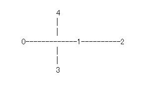
Exercise 2 : Multicast
Create a network which looks like the following:
Answer :
Tcl script :
set ns [new Simulator -multicast on]
# Dense Mode Multicast Protocol
set mproto DM
set mrthandle [$ns mrtproto $mproto {}]
# allocate a multicast address;
set group0 [Node allocaddr]
set group1 [Node allocaddr]
# Open nam tracefile
set nf [open prob1.nam w]
# Open tracefile
set nt [open trace.tr w]
$ns namtrace-all $nf
$ns trace-all $nt
$ns color 1 red
# the nam colors for the prune packets
$ns color 30 purple
# the nam colors for the graft packets
$ns color 31 green
#Define a 'finish' procedure
proc finish {} {
global ns nf nt
$ns flush-trace
close $nf
close $nt
puts "running nam..."
exec nam -a prob1.nam &
exit 0
}
# create 5 nodes
puts "create 5 nodes now....."
set n1 [$ns node]
set n2 [$ns node]
set n3 [$ns node]
set n4 [$ns node]
set n5 [$ns node]
puts "create connections now....."
# Create connection
$ns duplex-link $n1 $n2 1Mb 5ms DropTail
$ns duplex-link $n2 $n3 1Mb 5ms DropTail
$ns duplex-link $n3 $n4 1Mb 5ms DropTail
$ns duplex-link $n2 $n4 1Mb 5ms DropTail
$ns duplex-link $n2 $n5 1Mb 5ms DropTail
# Node orientation
$ns duplex-link-op $n1 $n2 orient right
$ns duplex-link-op $n2 $n3 orient right
$ns duplex-link-op $n3 $n4 orient right
$ns duplex-link-op $n2 $n4 orient down
$ns duplex-link-op $n2 $n5 orient up
puts "Create agents and attach to appropriate nodes..."
# Create agents and attach to appropriate nodes
set udp0 [new Agent/UDP]
$ns attach-agent $n1 $udp0
$udp0 set dst_addr_ $group0
$udp0 set dst_port_ 0
set cbr0 [new Application/Traffic/CBR]
$cbr0 attach-agent $udp0
set udp1 [new Agent/UDP]
$ns attach-agent $n3 $udp1
$udp1 set dst_addr_ $group1
$udp1 set dst_port_ 1
set cbr1 [new Application/Traffic/CBR]
$cbr1 attach-agent $udp1
puts "schedule transmitting packets..."
# create receiver agents
set rcvr0 [new Agent/LossMonitor]
set rcvr1 [new Agent/LossMonitor]
$ns attach-agent $n4 $rcvr0
$ns attach-agent $n5 $rcvr1
# joining and leaving the group;
$ns at 0.10 "$n4 join-group $rcvr0 $group0"
$ns at 0.12 "$n5 join-group $rcvr1 $group0"
$ns at 0.50 "$n4 leave-group $rcvr0 $group0"
$ns at 0.60 "$n4 join-group $rcvr0 $group1"
$ns at 0.05 "$cbr0 start"
$ns at 0.05 "$cbr1 start"
$ns at 0.80 "finish"
$ns run
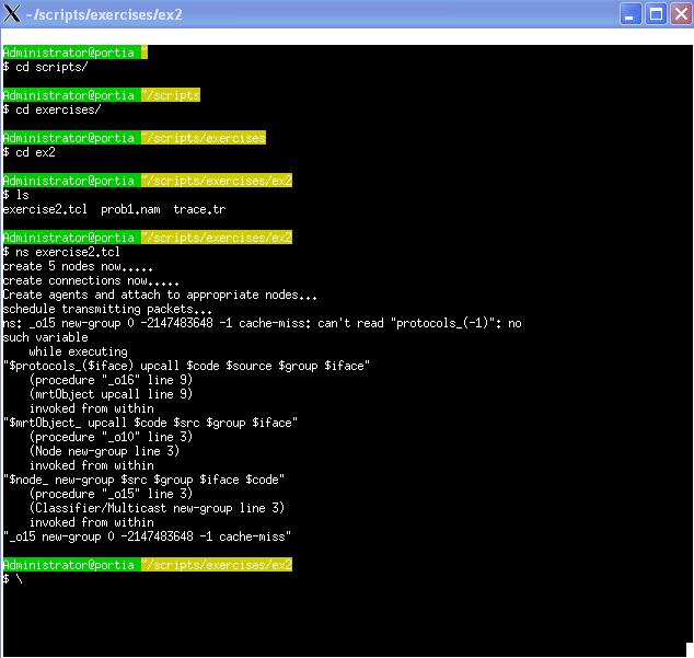
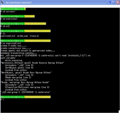
** Problem :
Unfortunately I ran into problem..still configuring what's wrong with the script :-( everything looks ok to me.. need to do some debugging!
Error :
ns: _o15 new-group 0 -2147483648 -1 cache-miss: can't read "protocols_(-1)": no
such variable
while executing
"$protocols_($iface) upcall $code $source $group $iface"
(procedure "_o16" line 9)
(mrtObject upcall line 9)
invoked from within
"$mrtObject_ upcall $code $src $group $iface"
(procedure "_o10" line 3)
(Node new-group line 3)
invoked from within
"$node_ new-group $src $group $iface $code"
(procedure "_o15" line 3)
(Classifier/Multicast new-group line 3)
invoked from within
"_o15 new-group 0 -2147483648 -1 cache-miss"

All links are 1 Mbps, 5 ms delay.
Choose DM (instead of CtrMcast) as the multicast routing protocol for the experiment. Node 0 is a UDP source for group 0 and node 2 is the source for group 1. The sources will start transmission at time 0.05. Nodes 3 and 4 will join the multicast group0 at times 0.10 and 0.12, respectively. Node 3 will leave the multicast group at 0.5, and then join group1 at 0.6. The execution will terminate at 0.8 sec.
Answer :
Tcl script :
set ns [new Simulator -multicast on]
# Dense Mode Multicast Protocol
set mproto DM
set mrthandle [$ns mrtproto $mproto {}]
# allocate a multicast address;
set group0 [Node allocaddr]
set group1 [Node allocaddr]
# Open nam tracefile
set nf [open prob1.nam w]
# Open tracefile
set nt [open trace.tr w]
$ns namtrace-all $nf
$ns trace-all $nt
$ns color 1 red
# the nam colors for the prune packets
$ns color 30 purple
# the nam colors for the graft packets
$ns color 31 green
#Define a 'finish' procedure
proc finish {} {
global ns nf nt
$ns flush-trace
close $nf
close $nt
puts "running nam..."
exec nam -a prob1.nam &
exit 0
}
# create 5 nodes
puts "create 5 nodes now....."
set n1 [$ns node]
set n2 [$ns node]
set n3 [$ns node]
set n4 [$ns node]
set n5 [$ns node]
puts "create connections now....."
# Create connection
$ns duplex-link $n1 $n2 1Mb 5ms DropTail
$ns duplex-link $n2 $n3 1Mb 5ms DropTail
$ns duplex-link $n3 $n4 1Mb 5ms DropTail
$ns duplex-link $n2 $n4 1Mb 5ms DropTail
$ns duplex-link $n2 $n5 1Mb 5ms DropTail
# Node orientation
$ns duplex-link-op $n1 $n2 orient right
$ns duplex-link-op $n2 $n3 orient right
$ns duplex-link-op $n3 $n4 orient right
$ns duplex-link-op $n2 $n4 orient down
$ns duplex-link-op $n2 $n5 orient up
puts "Create agents and attach to appropriate nodes..."
# Create agents and attach to appropriate nodes
set udp0 [new Agent/UDP]
$ns attach-agent $n1 $udp0
$udp0 set dst_addr_ $group0
$udp0 set dst_port_ 0
set cbr0 [new Application/Traffic/CBR]
$cbr0 attach-agent $udp0
set udp1 [new Agent/UDP]
$ns attach-agent $n3 $udp1
$udp1 set dst_addr_ $group1
$udp1 set dst_port_ 1
set cbr1 [new Application/Traffic/CBR]
$cbr1 attach-agent $udp1
puts "schedule transmitting packets..."
# create receiver agents
set rcvr0 [new Agent/LossMonitor]
set rcvr1 [new Agent/LossMonitor]
$ns attach-agent $n4 $rcvr0
$ns attach-agent $n5 $rcvr1
# joining and leaving the group;
$ns at 0.10 "$n4 join-group $rcvr0 $group0"
$ns at 0.12 "$n5 join-group $rcvr1 $group0"
$ns at 0.50 "$n4 leave-group $rcvr0 $group0"
$ns at 0.60 "$n4 join-group $rcvr0 $group1"
$ns at 0.05 "$cbr0 start"
$ns at 0.05 "$cbr1 start"
$ns at 0.80 "finish"
$ns run
** Problem :
Unfortunately I ran into problem..still configuring what's wrong with the script :-( everything looks ok to me.. need to do some debugging!
Error :
ns: _o15 new-group 0 -2147483648 -1 cache-miss: can't read "protocols_(-1)": no
such variable
while executing
"$protocols_($iface) upcall $code $source $group $iface"
(procedure "_o16" line 9)
(mrtObject upcall line 9)
invoked from within
"$mrtObject_ upcall $code $src $group $iface"
(procedure "_o10" line 3)
(Node new-group line 3)
invoked from within
"$node_ new-group $src $group $iface $code"
(procedure "_o15" line 3)
(Classifier/Multicast new-group line 3)
invoked from within
"_o15 new-group 0 -2147483648 -1 cache-miss"